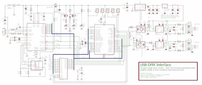
The USB-DMX interface's schematic. Click for bigger resolution.

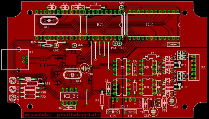
Top components and straps placement

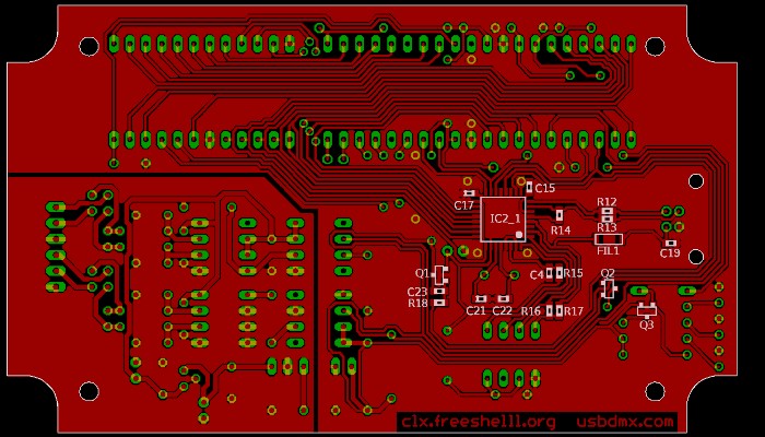
There are also few SMD components on the bottom side
I tried to keep the original names of most components in my schematic. There is the board's typon picture to be printed at 600dpi (be sure to print it at that resolution! and don't apply any mirrorring). You'll need to inject the bootloader before to solder the microcontroller or by ICSP directly by the pins mounted on the CI (mount them, they are useful). Okay now time for pictures ! The two first shows tricks in crystal placement and LEDs soldering.
When you'll be up to the knee in your ferric perchlorate bath, think that I did use a CNC to engrave the board ;)
More seriouly, I used a PIC16F877A because I had one (yup it's compatible). The plastic box I used (and for what the board's size is adapted) is one from Retex (serie 103, model 33103003). If you use the same XLR connectors than me, do not mount the 93Cx6 EEPROM on socket as the male connector is tall.
You can see the adapter in action in the second part of that youtube video, with the virtual serial port ethernetly delocalized by the use of ser2net on my home server running Linux Debian, and VSPE on my laptop. It's also possible to use directly with bash scripts or C code :
# initialyze the interface, sets channel 0 to 0xAA
# channel 1 to 0x10, and channel 4 to 0xFF
echo -en '\x44\x48\0\xAA\x48\x01\x10\x48\x04\xFF' > /dev/tty-usbdmx
EDIT 21/09/2014 :
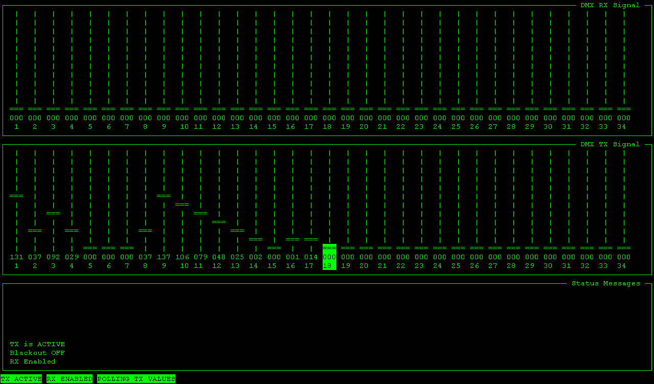
I wrote a little C program, based on ncurses, running on Linux or other Posix systems to simply set channels values with arrow keys, for example by SSH. Useful when I'm too lazy to execute DMXControl! Time to publish it!

make ; ./usbdmx /dev/tty-usbdmx