It is usable on Linux with lib-nfc and everything. We're using the USB-tty serial interface from Adafruit here, but you can use the one you want, as long the signal voltages are corrects. Something configurable is always better.
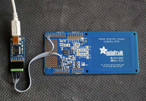
"FTDI Friend" board connected to the PN532 NFC/RFID Controller Shield, the both acting as a USB computer peripheral
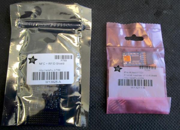
https://www.adafruit.com/product/789 and https://www.adafruit.com/product/284
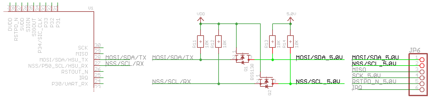
In the schematics (not supplied in PDF, so you need Eagle to look at it), we can see there is a voltage translation circuit, because it an Arduino board is running on 5V, and the PN532 IC is 3.3V. We have two options: communicating trough the level translation transistors and configuring the USB-serial interface to 5V, or connecting directly to the 3.3V TX and RX signals in between, and setting the USB-serial voltages to 3.3V.
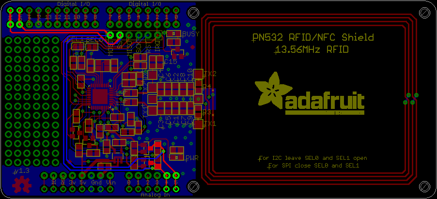
BRD board file opened with the Eagle software, allowing us to see were the 5V communication signals are routed.
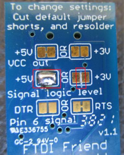
We choose the first option: using the level voltage translators, so we need the serial interface signals to be in 5V. With the "FTDI Friend" board, we needs to cut a track and to make a solder point to configure this. Also, the PN532 shield board is having its own 3.3V voltage regulator, so the power supply voltage is set to 5V in any case.
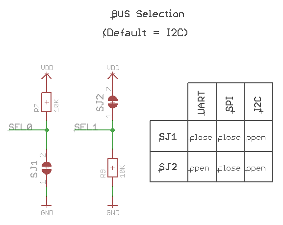
We need to configure the PN532 in UART mode. We also need the schematics to know how to do this, as the resistors circuit is making SEL0 high and SEL1 low by default (I²C mode).
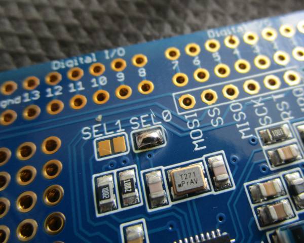
We only need to make a solder point on SJ1 for having both signals low (UART mode). On the PCB, it is noted "SEL0".
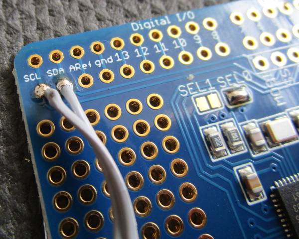
5V TX is annotated "SDA" and 5V RX is annotated "SCL" on the shield's silkscreen. Remember, one device TX goes to the opposite device RX and vice-versa.
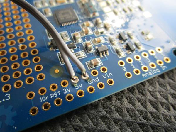
At least, there's no way to go wrong here...
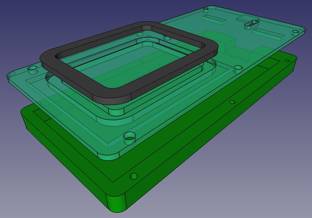
3D modelling of the enclosure parts with Freecad (project zip file)
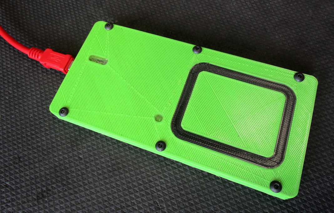
The assembled 3D printed enclosure with the boards inside